
Network redundancy
The underlying concept behind network redundancy is to provide alternate paths for data to travel along in case a cable is broken or a connector accidentally un-plugged. However, Ethernet as standard cannot have rings or loops in the network as this will cause broadcast storms* and can ultimately cause the network to stop working. An Ethernet network cannot have two paths from point A to point B without a mechanism in place to support this type of topology. To achieve redundancy, the network infrastructure (switches) must support redundancy protocols designed to negate the usual problems of putting loops into an Ethernet network, maintaining a default data path and switching to an alternate one when a fault occurs.
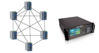
Classic star topology 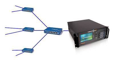
A typical Ethernet network employs a star topology as detailed in Figure 1 below.
There are several mechanisms for providing redundancy in a network, the most common being LACP*, RSTP* and ring redundancy. All switches must support the required redundancy capability and the switches must be connected to each other in an appropriate configuration.
For simplicity and ease of expansion, ‘redundant rings’ are becoming the most popular redundancy solution for the BMS market.
Redundant Ring topology 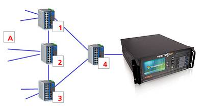
Using “Industrial Ethernet switches” it is possible to build a ring topology that can suffer a single point failure (cable broken or connector unplugged) and continue to operate as if nothing had changed. This will keep BMS controllers and outstations communicating with each other even in the event of a network failure. Comparing Figure 1 and Figure 2, the difference between a star and a ring network topology is clearly visible.
How does ring redundancy work?
 Consider Figure 2. The network traffic from outstation A follows the default path through the network from switch 2 to switch 1 to switch 4 to the destination - the Supervisor PC. If a cable is broken or a connector un-plugged along this default route, the switches will automatically reconfigure to transmit data the alternative way around the ring – switch 2 to switch 3 to switch 4 to Supervisor. This network reconfiguration can happen in as little as 20mS. Poorly designed redundant networks can have a much higher re-configuration time with BMS data potentially disappearing from the screen for several minutes. Without redundancy, the BMS system may stop working effectively for several days.
Figure 2 shows a network with redundancy at the “network layer” but no redundancy at the “device layer”. If the single link from the Supervisor to the network were broken, access to the live BMS data would be lost. The next logical step is to dual attach the Supervisor PC to the network removing the single point of failure. Dual attachment of Ethernet devices is not always a trivial process. Amplicon’s technical team can help with such requirements.
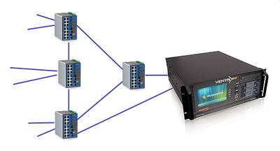
Redundant Ring topology with all devices dual attached 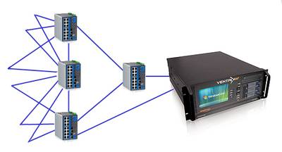
In highly critical applications, it may be necessary to dual attach all devices (outstations and PCs) to the network to provide a very high level of redundancy. This provides maximum reliability but also generates maximum cost and complexity.
Most vendors of Industrial Ethernet products support a version of the ‘redundant ring’ technology described above. It should be noted that the protocols used are not based on a standard and are generally not interoperable amongst the different switch manufacturers.
Spanning Tree
 TCP provides many network services but is best known for multiplexing, flow control and provision of an entry/exit point to the network. Applications (email, web browser, BMS software) access the network through ports*. By giving each piece of software its own port, it is possible to identify many different applications on a single network device and thus allow many applications on a single to use the same physical network without data getting delivered to the wrong place. This process is referred to as multiplexing as it allows many different data packets to be multiplexed over the network. At the receiving end, TCP de-multiplexes the data stream, distributing the right data packets to the correct applications.
Multiple paths exist between switches in a “mesh” providing a high degree of network redundancy.
Power redundancy
Many Industrial Ethernet switches support power redundancy, allowing 2 or more power inputs to be used in case of failure of the primary input. This can be a useful selling point for your network over a competitor’s solution and costs little extra to implement.