
Networking principles for the BMS market
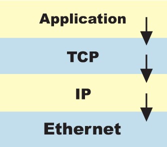
The following diagram shows the ‘Internet Protocol Suite’ found inside Ethernet enabled products. Although other protocols are involved, it is commonly referred to simply as TCP/IP as these are the defining protocols. Each protocol describes a set of rules by which participating devices in the network should operate and each device on the network must have all of these elements.
Ethernet is responsible for defining physical layer characteristics of the network such as:
Cables eg Category 5/5e/6 for copper based Ethernet
Connectors eg RJ45 connector
Signalling eg MLT-3 defines the voltage transitions used in 100 Base TX Ethernet
There is also a software element to Ethernet but it can primarily be considered the hardware or ‘physical’ layer.
Unlike Ethernet, the TCP/IP protocols are purely software applications executed by means of processor and RAM - just like any other piece of software. The TCP/IP implementation that we are most familiar with resides in the Windows operating system. It is installed by default on new PCs to provide internet, email and LAN connectivity as soon as the computer is turned on. This differentiation between hardware and software protocols is rarely pointed out but provides a much clearer indication of what is really happening in a protocol stack.
At the top of the stack is the ‘Application layer’. This is where TCP* (Transmission Control Protocol) aware software resides to run the device and to provide an interface to the network through the TCP layer. The application layer passes data to the TCP layer which in turn passes the information onto the IP* (Internet Protocol) layer and finally onto the Ethernet layer. This process is known as encapsulation* and is a precise term for what actually happens. The information from the layer above is encapsulated in the next layer until a fully functional Ethernet frame is formed. To help visualise the process, the Russian Dolls analogy is often used. The smallest doll represents a piece of data, the next doll the TCP layer, then the IP layer and the largest doll of all containing everything is Ethernet.
The receiving device on the network will go through the reverse process, stripping off the layers (technically known as headers) as the data is passed back up through the protocol suite with the ultimate goal of delivering just the data to the correct piece of application software.
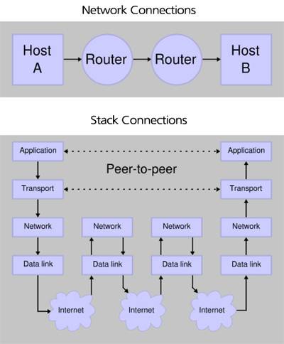 The "Network connections" diagram shows end to end communications between 2 devices on an IP network. Note that TCP is not involved in the intermediate stages as routers only need to know what IP address to forward the datagram to. Routers are not concerned with the data contained further up the stack. When the datagram arrives at the correct IP address, TCP then distributes data to the relevant application.
Why so many protocols?
From a practical point of view, networking could be made a lot more simplistic if we combined and renamed the TCP, IP and Ethernet protocols as just ‘Protocol X’ – treating it as just one all encompassing but more complex entity. It would be a more tangible concept for newcomers to the technology making a basic level of understanding easier to achieve. However, if we look in a bit more detail its clear that each protocol plays a key role in providing a reliable end to end data delivery mechanism.
Over the years, many competing protocols have battled for dominance. Token ring once offered a commercially viable alternative to Ethernet. IPX / SPX used to be an alternative to TCP/IP. Commercial developments have helped to define a much clearer networking landscape these days. Ethernet is by far the most cost effective LAN* solution and TCP/IP is now the language of the internet, so many of the alternatives have fallen by the wayside. It is for this reason that we will focus exclusively on TCP/IP and Ethernet in this guide.
Ethernet
The Ethernet we know today is very different to the original standard. It is a ‘living’ protocol that is permanently evolving. Ethernet defines the physical characteristics of the network connection – cables, connectors and the type of signalling protocol used.
There are many variants of Ethernet each with their own set of rules. Wireless Ethernet, fibre optic Ethernet and copper Ethernet are all commonplace. It is worth remembering at this point, that regardless of which type of Ethernet we are using its fundamental purpose and capability is the same. It encapsulates TCP/IP and its data payload and facilitates the physical transmission of information from one point in a network to another. The Ethernet variants most commonly used for BMS systems are detailed below.
100 Base Tx is the predominant form of fast Ethernet (100Mbps), and uses two pairs of a category 5* or category 6* cable. A typical category 5 / 6 cable contains 4 pairs and can therefore support two 100 Base Tx links. The cable is terminated with RJ45 connectors according to the pin-out defined in the standard. The raw data rate of 100Mbps is identified in the title – ‘100’ Base Tx.
100 Base Fx is a specification for Ethernet over optical fibre at 100Mbps. Using fibre extends the range of an Ethernet connection to 2km on multimode fibre, although much greater distances can be achieved using singlemode fibre. Non-electrical transmission of data provides electrical isolation and noise immunity. In some applications, the benefits of using fibre optic cabling far outweighs the additional costs of installing an optical transmission medium.
1000 Base T is a standard for gigabit Ethernet over copper wiring. It uses Category 5 twisted pair cable as a minimum but Category 5e and Category 6 cable is preferred. 1000 BASE T uses all 4 twisted pairs in the cable.
1000 BASE SX is a standard for gigabit Ethernet over fibre optic cabling. It operates over multimode* fibre optic cable with a specified distance capability up to 220m using 62.5/125µm fibre. The range increases to 500m with 50/125µm fibres. 1000 Base SX is the lowest cost fibre optic technology for gigabit speeds.
1000 BASE LX defines a standard for gigabit fibre optic connections over several kilometers using singlemode* fibre. All implementations of Ethernet over fibre require a dedicated strand for Transmitted data and one for received data providing a full duplex* connection. Specialist products are available that allow a single strand of fibre to be used for full duplex communications. This can be extremely useful when only a single fibre is available or the installed fibre is deemed to be a very precious commodity.
The trade-off of bandwidth, cost and distance are the key considerations when choosing the particular type of Ethernet your application will use. An understanding of the basic Ethernet standards enables you to select hardware that supports the correct network interfaces and to specify the right type of cabling. For example, you may need an Ethernet switch with 4 x 100 Base TX RJ45 copper ports for connecting to outstations and 2 x 1000 Base SX ports to provide high bandwidth fibre-optic backbone connections to other switches in the network.
As a rule of thumb, BMS Systems will tend to use low-cost copper cabling wherever possible with runs of fibre-optic cable where the cable paths exceed 100m or must traverse electrically noisy environments. It may be necessary to route data cables through trays or ducts containing existing power cables. In this instance, fibre may be the only solution that provides a working communications link. Some installers choose to use Shielded Twisted Pair* (STP) cable instead of Unshielded Twisted Pair* (UTP) as a cheaper solution than implementing a fibre-optic system. STP provides additional interference immunity (because of the shield!) at a fraction of the cost of fibre. If you do use STP – remember to ground the shield!
Ethernet Hardware
 There are two distinct types of Ethernet hardware that are important to the Building Controls market. The communicating devices - supervisor PCs, outstations and controllers – are a well defined set of devices produced by the BMS manufacturers and known to be fully interoperable and compatible. However, the network infrastructureequipment – hubs, switches, routers and cabling are not defined and this is where there is scope for selection of unsuitable products or ones that simply will not work as expected.
The most important tool available to integrators and installers is the Ethernet switch*. Switches are the underlying glue in any BMS network that allow all the different Ethernet devices to communicate with each other. Switches connect to devices and to other switches via fibre optic or copper cables at so many millions of bits of data per second (Mbps) depending on the particular type of Ethernet ports available on the switch – see the Ethernet section on page X for more details. This provides physical connectivity from one end of the network to the other.
Ethernet hubs* used to provide a more cost-effective connectivity solution but the inefficient nature of their operation and falling prices of switches has led to them becoming obsolete. Whilst you may find a hub in an existing network, only switches should be considered for new projects.
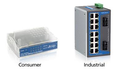
The ‘Industrial Ethernet switch’* is an increasingly popular solution for BMS Systems where reliability and ease of installation are key. Industrial Ethernet switches are typically powered directly by 24Vdc and have a DIN-rail mount bracket making them much more suited to the environments into which they are installed. Their general construction is of a much higher quality with longer warranties than their consumer counterparts (typically 5 years). ‘Industrial Ethernet’ switch prices have fallen dramatically over recent years meaning that a superior networking solution is now available for only a few 10s of pounds more.
Another key benefit of ‘Industrial Ethernet switches’ is the ability to build redundant networks – networks that have built-in fault tolerance. By selecting the appropriate switch and changing a few configuration parameters it is possible to demonstrate to your customer that your solution is highly reliable. This can be a major selling point over a competitor or could simply be a pre-requisite of the tender specification. The ability to explain how you would build a redundant network may separate you from your competition in the BMS world. The following section steps through the levels of redundancy that you may need to consider.
IP - Internet protocol
The Internet Protocol provides a number of services that enable communications between multiple devices in a network. The most well known of these services are addressing and routing. The Internet Protocol provides the logical addressing system for the internet and the vast majority of Ethernet LANs hence data can be sent seamlessly to computers and devices around the world.
A typical BMS network will require you to have a basic operating knowledge of IP addresses – knowing what ranges are valid for a private network and the basic rules of sub-netting to make sure all your devices can talk to each other.
Private IP address ranges
Most Ethernet hardware (outstation / controller) will have a default IP address in the following address ranges:
192.168.0.0 to 192.168.255.255
10.0.0.0 to 10.255.255.255
172.16.0.0 to 172.16.255.255
These three network address ranges are reserved for private networks and are specifically assigned for you to use for privately operated networks that do not directly interface to the internet. A typical BMS system may have statically assigned IP addresses from 192.168.1.1 to 192.168.1.254 with the supervisor PC sitting on 192.168.1.1. This is a perfectly valid configuration and quite a rudimentary scheme to implement but consideration must be given not only to the IP address of each device on the network but also to it’s subnet mask*.
A subnet mask defines which part of the network address range can be used by the communicating equipment. The entire topic of sub-netting is a well described process in many text-books or websites but is outside the scope of this document. As a simple rule of thumb, always use the following combination if you have less than 255 devices on your network and there are no other devices that you need to consider:
Use IP addresses from 192.168.1.1 to 192.168.1.254 (Note that 192.168.1.0 is the network ID of the subnet and 192.168.1.255 is the broadcast address – neither of these should be used)
For all devices, use a subnet mask of 255.255.255.0.
TCP - Transmission control protocol
TCP provides many network services but is best known for multiplexing, flow control and provision of an entry / exit point to the network. Applications (email, web browser, BMS software) access the network through ports*. By giving each piece of software its own port, it is possible to identify many different applications on a single network device and thus allow many applications on a single to use the same physical network without data getting delivered to the wrong place. This process is referred to as multiplexing as it allows many different data packets to be multiplexed over the network. At the receiving end, TCP de-multiplexes the data stream, distributing the right data packets to the correct applications.
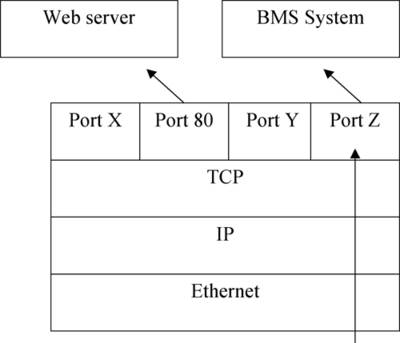 The diagram on the right shows an Ethernet frame being de-encapsulated. The frame has arrived at the correct IP address but there is still a further differentiation to be made – which application requires the data? The relevant software application is identified by its TCP port number. It is through ports that all data gets into and out of an IP network.
It is common to talk of client / server architecture within networking applications, a terminology derived from the way TCP builds and maintains connections. A TCP client (a supervisor PC running BMS software for example) initiates connections to a TCP server (outstation / controller) through a process known as the three-way handshake. In this exchange, a TCP client makes a connection request, the server acknowledges the request and the client acknowledges the server’s acknowledgement. From this point onwards, an end to end connection between client and server exists and bi-directional transfer of data is possible. This type of connection is also referred to as a Virtual Circuit as it is equivalent to having a full duplex point to point connection between two end devices (similar to an RS232 connection but faster) even if they are many miles apart and pass through many different types of network.
TCP is commonly referred to as a connection orientated protocol because of the way it builds a virtual circuit prior to communication between network devices. TCP also checks that every single byte of data sent has been received through an on-going succession of acknowledgements. Because of this, TCP is considered to be reliable but relatively slow. For faster network communications, the UDP* protocol is used in place of TCP. The addressing concept of ports remains true for UDP but it is not encumbered by the three way handshake and on-going error checking.
What if a UDP message is lost in the network? Nothing – it is lost and will not automatically be re-sent. For this reason, UDP is often used for voice and audio streaming applications where speed of transfer is key and the occasional lost packet will just cause a slight glitch in the video image or sound quality. Most BMS Systems do not need high data transfer speeds but do need reliable connections hence TCP will typically be driving your BMS communications.